Topics
Working with Objects
All objects, including Pictures, Drawing Shapes and Text Boxes interact with each other in predictable ways. For example objects can be:
- Grouped together so they can be manipulated/formatted as one object
- Arranged in a different stacking order
- Aligned with each other in specific ways
- Spaced apart from each other at specific intervals
- Flipped horizontally and/or vertically
- Positioned at a specific spot on the slide
- Rotated in different ways
- Slanted in different directions
Group/Ungroup Objects
All objects can be Grouped together regardless of their type. When objects are grouped together they stay in the same relative position to each other. Clicking on any of the objects in the group selects the whole group. Any number of objects can be grouped. It doesn't matter if the objects overlap each other or not. When objects are grouped they act as one object.
When objects are Grouped together:
- The selection handles are applied to the group.
 The group can be moved around on the slide as one object.
- The group can be scaled together as one object.
- Their colour/outline can be changed together as a group.
Selecting, Grouping/Ungrouping Objects
Selecting Objects
Before objects can be grouped, they need to be selected first. To select objects to be grouped:
 Hold down the Shift key and select all the objects to be grouped. As each object is selected the Selection Handles expand over that object.
 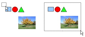 Use the Pointer to create a Selection Net to capture all objects to be grouped. The use the Pointer properly start above the upper most left object and click and hold down the Left mouse button and drag over to the lowest right object to be grouped. The Selection Net must completely enclose an object in order for it to be "caught" in the net. If the net only brushes over part of an object, that object will not be selected.
Grouping/Ungrouping Objects
When the objects are grouped together, their Selection Handles are green. Objects can be Grouped or Ungrouped by:
 The right click Context Menu
- The Modify Menu: MODIFY-> GROUP or MODIFY-> UNGROUP
- The Keyboard Shortcut: CTRL+SHIFT+G to Group and CTRL+ALT+SHIFT+G to Ungroup
Objects can be temporarily grouped just by selecting them. While in this temporary group they can be moved, scaled or coloured as one object. Once deselected they are returned to individual objects.
Enter/Exit Group
A common problem with ungrouping objects to make a quick change is that objects can get accidentally moved out of position, particularly if they overlap each other. The Enter Group command allows you to enter the group and modify each object individually within the group without affecting the other objects within the group. Any modification can be done including changing their colour/outline, scaling, changing the stacking order, and even deleting objects within the group. You can still use the Shift key or Selection Net to select multiple objects within the group to modify multiple objects at the same time.
To Enter and Exit a Group:
- Right click Context Menu
- Modify Menu: MODIFY->ENTER GROUP or MODIFY->EXIT GROUP
- The Keyboard Shortcut: F3 to Enter Group and CTRL+F3 to Exit group
- Double click on the slide to Exit the Group
 When a grouped object is entered all other objects on the page "dim" out. Each object in the group can now be selected individually (or multiple selection can be made) and modified. Any number of objects within the group can be modified or deleted. Existing the group returns everything back to normal.
Arrange Command
Arrange Button
 Every object added to the slide is placed on a separate stacking order. Each new object added is placed one higher in the stacking order. In other words, the first object placed on the slide is at the bottom of the stacking order and the last object placed is at the top of the stacking order. No two objects can occupy the same stacking order even if grouped. Regardless where an object exists in the stacking order it can be moved up or down the stacking order.
Objects are moved through the stacking order with the Arrange command. To access the Arrange command:
- Right click for the Context menu
- Modify Menu: MODIFY-> ARRANGE
- The Arrange Button on the Drawing toolbar
- Keyboard shortcuts, there are a variety of Arrange shortcuts with the two most common: Bring to Front - "CTRL+SHIFT+ +" and Send to Back - "CTRL+SHIFT+ -".
Red Circle 1: Bring Forward, the Circle moves up one level in the stacking order
Red Circle 1: Bring to Front, the Circle moves to the top of the stacking order.
Blue Square 4: Send Backward, the Square moves down one level in the stacking order
Blue Square 4: Send to Back, the Square goes to the bottom of the stacking order
Reverse: all objects reverse their stacking order
There are four basic Arrange commands, two selectable Arrange commands and one Arrange command to completely reverse the stacking order. The four basic Arrange commands are self explanatory: Bring to Front, Bring Forward, Send Backward and Send to Back. The two selectable commands: In Front of Object and Behind Object allow you to place an object specifically in Front or Behind any other object in the stacking order. The Reverse command does exactly that, it reverses the stacking order.
 The two selectable commands, In Front of Object and Behind Object, allow you to select where in the stacking order you wish to send an object. Unlike the other Arrange commands these two commands require a couple of extra steps:
- Select your object
- Choose either command (in this case the Behind Object command is used)
- The Arrow icon changes to a Pointing Hand icon
- Hover over the object you wish to move behind (or in front of) and that object's outline becomes a "dashed outline" indicating your choice and click on it.
- Your object moves in the stacking order
Aligning Objects

Alignment Button
Objects can be aligned with each other either vertically or horizontally . The objects to be aligned need to be selected but not grouped. If the objects are grouped the Align command will apply to grouped object and its alignment to the slide. The Alignment Commands can be accessed through:
- Right click Context menu
- Modify menu: MODIFY-> ALIGN
- The Alignment Button on the Drawing toolbar
Horizontal Alignment
 The Horizontal Alignments move objects left or right not up and down. The vertical positioning of the objects remain the same. There are three Horizontal Alignments:
- Left: all objects are aligned to the object that is furthest to the left. In other words all the left edges of the objects are aligned to the left edge of the object that is furthest left.
- Center: all objects are aligned to the centre point of the object that is most centred amongst them.
- Right: all objects are aligned to the object that is furthest to the right. In other words all the right edges of the objects are aligned to the right edge of the object that is furthest right.
 In this illustration, the dashed lines indicates how the objects are aligned. Notice that the objects vertical position doesn't change. The objects only move horizontally as indicated. If the objects are Grouped the group will align to the slide, i.e. Alignment Left would align the group to the left edge of the slide.
Vertical Alignment
The Vertical Alignments move the objects up or down not left and right. The horizontal positioning of the objects remain the same. There are three Vertical Alignments:
- Top: all objects are aligned to the top object. In other words all the top edges of the objects are aligned to the top edge of the object that is furthest to the top.
- Center: all objects are aligned to the centre point of the object that is most centred amongst them.
- Bottom: all objects are aligned to the object that is furthest to the bottom. In other words all the bottom edges of the objects are aligned to the bottom edge of the object that is furthest to the bottom.
 In this illustration the dashed lines indicates how the objects are aligned. Notice that the objects horizontal position doesn't change. The objects only move vertically as indicated. If the objects are Grouped the group will align to the slide, i.e. Alignment Top would align the group to the top edge of the slide
Slide Alignment
 When a single grouped object has an Alignment Command applied to it, the Alignment is based between it and the slide. In other words if a single grouped object had a vertical Top Alignment applied to it, that object would be aligned to the top of the slide.
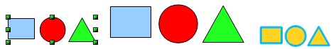
This illustration demonstrates the Alignment command on a grouped object. The original grouped object is the one with the Selection Handles. The three horizontal Alignments commands of Left, Center and Right are applied to the grouped object and its three horizontal Alignment positions relative to the slide are shown.
The vertical Alignment Commands of Top, Center and Bottom are applied the grouped object and its three vertical Alignment positions relative to the slide are also shown.
If multiple grouped objects are selected then the Alignment commands behave as they do with single multiple objects selected.
Spacing Distribution
The Distribution Command distributes space amongst selected objects. If the objects are all the same size then the empty space between then will be equal. When distributing space amongst objects, the first and last objects remain in position and all the other objects are spaced between them.
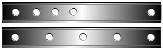 In this illustration of a steel beam an even distribution of the circular rivet holes are needed. The top image shows that the 5 rivet hole circles are not evenly spaced. The second image has a Horizontal Distribution applied to the 5 rivet hole circles and as shown the middle circles are evenly distributed between the first and last Circles.
The Distribution Command can be accessed through:
- The right click Context menu
- The Modify Menu: MODIFY-> DISTRIBUTION
There are 4 Horizontal and 4 Vertical Distribution Commands. If the objects are all the same size, regardless of which of the Horizontal/Vertical options are chosen the spacing between the objects will always be identical.
Horizontal Distribution
As the name implies the spacing is applied Horizontally (left/right) amongst the selected objects. The four options are:
- Left:
 This spacing measurement is taken from the Left edge of all objects. If the objects have different widths then the actual empty space between each object will not be the same, even though their left edges are evenly spaced from each other.
- Center:
 This spacing measurement is taken from the Centre of all objects. If the objects have different widths then the actual empty space between each object will not be the same even though their horizontal centres are evenly spaced from each other. In the first example the blue square and the green circle have the same width and as such the empty space between them and red rectangle is identical. In the second example all three shapes have different widths and although they are still evenly spaced from their horizontal centres, the actually empty space between each object is not the same.
 - Spacing:
 This spacing measurement Evenly distributes the Horizontal empty space between each object regardless of their widths. Therefore all objects will have the same amount of empty space between them.
 - Right:
 This spacing measurement is taken from the Right edge of all objects. If the objects have different widths then the actual empty space between each object will not be the same, even though their right edges are evenly spaced from each other.
Vertical Distribution
As the name implies the spacing is applied Vertically (top/bottom) amongst the selected objects. The four options are:
- Top:
 This spacing measurement is taken from the Top edge of all objects. If the objects have different heights then the actual empty space between each object will not be the same, even though their top edges are evenly spaced from each other.
 - Center:
 This spacing measurement is taken from the Centre of all objects. If the objects have different heights then the actual empty space between each object will not be the same even though their vertical centres are evenly spaced from each other. In the first example the blue square and the green circle are almost the same height and therefore are almost evenly spaced from the red rectangle with almost the same amount of empty space. In the second example all three shapes are different heights and although they are still evenly spaced from their vertical centres, the actually empty space between each object is not the same.
 - Spacing:
 This spacing measurement Evenly distributes the Vertical empty space between each object regardless of their heights. Therefore all object will have the same amount of empty space between them.
 - Bottom:
 This spacing measurement is taken from the Bottom edge of all objects. If the objects have different heights then the actual empty space between each object will not be the same, even though their bottom edges are evenly spaced from each other.
In this illustration demonstrating the 4 options of Horizontal Distribution, two sets of objects are compared: objects with different widths (top row of objects) and objects having the same width (bottom row of objects). In the top row of objects, the only way to get the same empty space between each object is with the Spacing options. In the bottom row all objects have the same amount of empty space regardless of the Distribution option used because all the objects have the same width.
Flipping Objects Horizontally/Vertically
 All objects, including Drawing Shapes and pictures can be flipped horizontally and/or vertically. Flipping an object produces a mirror image of that object. For example you may be creating a poster or flyer and the picture image doesn't face the way you would like it to face. By flipping the picture horizontally you get the mirror image. In this example a of a poster, the poster on the left contains the original picture and the poster on the right has the pictured flipped. Because we "read" left to right, the poster on the right makes a stronger impression because the trees lean into the direction that we read which brings the reader "into" the poster. The poster on the left has the trees leaning to the left which takes the reader "out" of the poster.
 Even though all Drawing Shapes can be flipped, a Drawing Shape containing text incurs a bit of a problem. Flipping a shape containing text horizontally doesn't flip the text horizontally. As matter of fact nothing happens to the text, it stays the same. Strangely enough, however, if the Drawing Shape is flipped vertically, the text will flip vertically with the shape, although its not really a mirror image, but a 180 degree rotation.
Position and Size
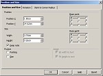 The Position and Size dialogue box allows you to precisely scale, position and rotate objects on the slide. You can also slant objects (skew) and apply rounded corners to a rectangle created via the Rectangle tool. This box contains 3 tabs:
- Position and Size: Allows for the exact positioning and/or precise sizing of an object. Objects can also be "Protected" (locked) from being moved and/or resized.
- Rotation: Allows for the precise rotation of an object around a "Pivot Point".
- Slant & Corner Radius: Precisely slants an object and also allows for a corner radius to be applied to a rectangle that was created using the Rectangle tool.
Position and Size Tab
Position
 The first section in this tab is the Position section. To precisely positioned an object on a page a target area on the object, referred to as the Base Point, is required to act as reference point for the positioning. The default Base Point is the Top left which is the top left corner of the object but, as shown there are 9 possible Base Points. An objects sizing handles pretty well indicate the location of all the Base points, except for the centre.
The Position X (horizontal) and Position Y (vertical) refers to the position of the Base Point on the slide. If the Position X and the Position Y are both set to "0", then the Base Point of the object moves to the 0:0 coordinates on the slide which is top left corner of the Text Boundary (not the top left corner of the slide). Its important to set the Base Point first before changing the Position X/Y coordinates. In the following illustration the Position X and Y are set at 0:0, which is the top left corner of the Text Boundary.
The red circles placed over the sizing handles indicates the object's Base Points. The Position X and Y for each Base Point were set at 0 which is the top left corner of the Text Boundary box. Note how the different Base Points truly effect the object's positioning.
Size
 The Size section allows you to precisely size (scale) an object based from any of the 9 Base Points. By default the Top Left Base Point is selected. Also by default the Keep Ratio is checked. You always want to ensure that the Keep Ratio is checked because it locks the Width/Height ratio together so that only one measurement needs to be modified and the other will proportionally change automatically. By default the top Base Point is selected when sizing an image, the following illustration demonstrates how the Base Point effects the position of the sized object.
In the Original example the red Square and blue Circle are the exact same size. In the other 5 examples the Circle is reduced to 50% of its original size. The different positions of the Circles in the Squares relates directly to which Base Point was selected. Therefore the Base Point dictates the position of the resized object.
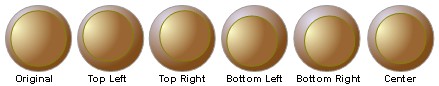 Sometimes the selection of the Base Point is important when resizing an object. For example in this illustration two gradient filled Circles are used to create a navigational button for a website as show in the Original sample. If the top smaller Circle needed to be a bit smaller, the Base Point chosen for the resize makes a major difference to the look of the button. In this case only the Centre Base Point works.
Protect

 The Protect section locks the size and/or position of an object. There are two options:
- Position: If the Position option is checked the object can neither be moved nor resized. Checking the Position option automatically checks and greys out the Size option so that the Size option can not be unchecked.
- Size: If only the Size option is checked then only the size is Protected (locked) not the positioning.
When the mouse pointer is placed over any sizing handle on a Protected object, the pointer changes to the Protect icon.
Rotation Tab
Pivot Point
![]() The first section of this tab the Pivot Point. The Pivot Point is the point over which the object rotates around. The distance to the Pivot Point is indicated by the Position X/Y. Selecting a Pivot Point displays its coordinates in the PositionX/Y. Selecting a Pivot Point without changing the PositionX/Y position means the object rotates around itself at that Pivot Point. If a greater PositionX/Y distance is used, then the object's Pivot Point rotates over a larger arc. An object can be rotated either through the Rotation Angle section or manually by using the Rotate tool found on the Drawing toolbar.
The first section of this tab the Pivot Point. The Pivot Point is the point over which the object rotates around. The distance to the Pivot Point is indicated by the Position X/Y. Selecting a Pivot Point displays its coordinates in the PositionX/Y. Selecting a Pivot Point without changing the PositionX/Y position means the object rotates around itself at that Pivot Point. If a greater PositionX/Y distance is used, then the object's Pivot Point rotates over a larger arc. An object can be rotated either through the Rotation Angle section or manually by using the Rotate tool found on the Drawing toolbar.
In this illustration the Original sample shows a blue Arrow Shape placed inside a red Square of equal size. The Arrow is then rotated 45 degrees using five different Pivot Points. The small red circles mark the Pivot Points. As shown the different Pivot Points clearly influence the Arrow Shape's position as it rotates around the Square.
Rotation Angle
The 8 Default Rotation Settings applied to Top Left Pivot Point indicated in red.
 The second section is the Rotation Angle. There are eight Default Angles to click on: 0, 45, 90, 135, 180, 225, 270 and 315. However any angle value can be set by either spinning a number with the Spin arrows or typing the number in the Spin box.
The illustration to the right demonstrates the Default Rotation angles as applied to a single Pivot Point. Each Arrow Shape represents one of the Default Rotation Angles applied to the Top Left Pivot Point. The Top Left Pivot Point is indicated by the red circle.
Increasing the Position X/Y Distance
 If the PositionX/Y is increased then the objects's Pivot Point rotates around a larger arc. In this illustration each Arrow Shape's PositionX/Y coordinates were set to the centre of the page (which is indicated by the red Circle at the centre of the page). The Center Pivot Point is selected for each Arrow Shape (indicated by the red Circle on each shape). The degree of rotation for each Arrow Shape is indicated. As shown each shape's Pivot Point rotates over a large arc which is created by the distance between the PositionX/Y coordinates and the shape's Pivot Point (indicated by the red connecting lines).
It doesn't really matter which shape's Pivot Point was actually selected, all the shapes will rotate in exactly the same arc as long as the distance to the PositionX/Y remains the same. Diagrams, such as a Radial diagram can easily be created in this manner. If the PositionX/Y coordinates are too great, then the shapes may rotate completely off the slide.
Slant & Corner Radius Tab
Corner Radius
![]()
![]() The first section of this tab is the Corner Radius. This option is limited to a rectangle created with the Rectangle Tool or a text box created with the Text Tool on the Drawing toolbar.
The first section of this tab is the Corner Radius. This option is limited to a rectangle created with the Rectangle Tool or a text box created with the Text Tool on the Drawing toolbar.
The Corner Radius is applied in small increments, the amount used depends on whether the shape is a Square or Rectangle and the shape of the rectangle. In this example anything under 1cm will produce a corner radius. Anything over 1cm will just produce an oval shape as shown.
Slant
![]() The second section is the Slant option. Just about any vector object can be slanted except a text box created with the Text tool. Ironically, if a Drawing Shape containing text is slanted the text will slant also. Positive numbers slant to the Right, Negative numbers slant to the Left. If the angle of degree goes beyond 80, most object will slant down to almost a flat shape that resembles a very long line. Pictures can not be slanted unless they are first converted to a Curve. If a shape contains a Bitmap Fill, the shape will slant but not the Bitmap fill.
The second section is the Slant option. Just about any vector object can be slanted except a text box created with the Text tool. Ironically, if a Drawing Shape containing text is slanted the text will slant also. Positive numbers slant to the Right, Negative numbers slant to the Left. If the angle of degree goes beyond 80, most object will slant down to almost a flat shape that resembles a very long line. Pictures can not be slanted unless they are first converted to a Curve. If a shape contains a Bitmap Fill, the shape will slant but not the Bitmap fill.
As shown in this illustration, as the degree of slant increases so does the elongation of the shape to the point where it becomes almost a line at 90 degrees. The 90 degree line is shown here in a truncated form, as it actually becomes a very long flat shape resembling a line.
![]() If the slanted shape is stretched horizontally or vertically it retains the angle of the slant.
If the slanted shape is stretched horizontally or vertically it retains the angle of the slant.
Conclusion
Basic commands such as Group, Align, Distribution and Arrange are essential when working with objects. A fundamental knowledge in these areas go a long way in making your next project easier to handle.
Comments or suggestions: lincpark@hotmail.com.